Background: Radiation shielding primarily is based on the principle of attenuation of beams of X-ray or gamma radiation by absorption or scattering of the radiation that results due to the interaction between penetrating radiation and matter, radiation shielding properties such as attenuation coefficients obtained as a result of interaction between X-rays and gamma rays with target materials helps to study and confirm the appropriate building materials used for radiation shielding purposes. The linear attenuation coefficient required by radiation engineers in the design and analysis of radiation facilities has been determined and analysed for both gamma ray source Cs-137 and X-ray sources for 662 keV and 60- 120 kVp respectively. Methods: The determination of linear attenuation coefficient was evaluated by the formulation of building materials such as lead, granite, aluminium and concrete by calculating and comparing both experimental and theoretical results for 662 keV and 60-120 kVp using collimated Source-Material-Detector geometry method and XCOM software respectively. Conclusion: The results agreed with similar experimental works and the use of XCOM software with a percentage deviation of 0.44% - 11% at the 95 % confidence level. It was concluded that the results will go in a long way in assisting engineers and radiation professionals in the design and protection of radiation facilities.
| Published in | Radiation Science and Technology (Volume 10, Issue 1) |
| DOI | 10.11648/j.rst.20241001.12 |
| Page(s) | 11-20 |
| Creative Commons |
This is an Open Access article, distributed under the terms of the Creative Commons Attribution 4.0 International License (http://creativecommons.org/licenses/by/4.0/), which permits unrestricted use, distribution and reproduction in any medium or format, provided the original work is properly cited. |
| Copyright |
Copyright © The Author(s), 2024. Published by Science Publishing Group |
Linear Attenuation, X-rays, Gamma Ray, XCOM
CONCRETE CODE | QUARRY DUST (g) | CEMENT (g) | RIVER SAND (g) | WATER (g) | W/C RATIO | MIXING RATIO |
|---|---|---|---|---|---|---|
CSQW (C1) | 800 | 100 | 400 | 90 | 0.90 | 1:4:8 |
CQW (C2) | 0 | 800 | 2400 | 549.6 | 0.69 | 1:3 |
CSW (C3) | 2100 | 700 | 0 | 500 | 0.71 | 1:3 |
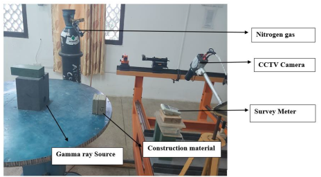
2.1. Cs-137 Irradiation
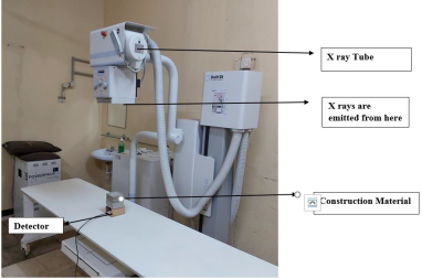
2.2. X-Ray Irradiation
kVp | kVp Average | % Error | Pass/Fail |
|---|---|---|---|
60 | 60.9 | 1.5 | Pass |
70 | 71.0 | 1.4 | Pass |
80 | 80.6 | 0.7 | Pass |
90 | 90.8 | 0.9 | Pass |
100 | 100.6 | 0.6 | Pass |
120 | 120.3 | 0.2 | Pass |
kVp Average | Time (msec) | Dose (µGy) | |
|---|---|---|---|
80.6 | 50.5 | 239.5 | |
80.6 | 50.0 | 239.8 | |
80.3 | 50.5 | 241.0 | |
80.6 | 51.0 | 240.1 | |
80.7 | 51.0 | 239.2 | |
81.1 | 51.0 | 240.2 | |
Average | 80.66 | 50.67 | 239.9667 |
CV | 0.0032 | 0.0081 | 0.0026 |
P/F | Pass | Pass | Pass |
mAs | Dose (µGy) | µGy/mAs | CV | P/F |
|---|---|---|---|---|
4 | 270.6 | 67.650 | - | - |
8 | 545.2 | 68.150 | 0.004 | Pass |
16 | 1027 | 64.188 | 0.030 | Pass |
32 | 2047 | 63.968 | 0.002 | Pass |
64 | 4085 | 63.828 | 0.001 | Pass |
125 | 8200.6 | 65.605 | 0.014 | Pass |
Sample | Thickness (mm) | Density (g/cm3) | Linear attenuation µ (cm-1) | Mass attenuation µm (cm2/g) | Half value layer (cm) | Tenth value (cm) | Mean free path (cm) |
|---|---|---|---|---|---|---|---|
Lead | 1.5 | 11.3612 | 1.5026 ± 0.058 | 0.1323 ± 0.0051 | 0.4613 | 1.5324 | 0.6655 |
3.0 | 1.3911 ± 0.033 | 0.1224 ± 0.0029 | 0.4983 | 1.6555 | 0.7189 | ||
4.5 | 1.3273 ± 0.025 | 0.1168 ± 0.0022 | 0.5222 | 1.7348 | 0.7534 | ||
Aluminium | 6 | 2.7189 | 0.1998 ± 0.005 | 0.0735 ± 0.0020 | 3.4692 | 11.5244 | 5.0050 |
8 | 0.2016 ± 0.003 | 0.0741 ± 0.0014 | 3.4382 | 11.4216 | 4.9603 | ||
10 | 0.1962 ± 0.003 | 0.0722 ± 0.0014 | 3.5329 | 11.7359 | 5.0968 | ||
Granite | 20 | 2.6567 | 0.1952± 0.0029 | 0.0735 ± 0.0018 | 3.5510 | 11.7960 | 5.1230 |
40 | 0.1924± 0.0036 | 0.0724 ± 0.0019 | 3.6026 | 11.9677 | 5.1976 | ||
60 | 0.1874 ± 0.0032 | 0.0705 ± 0.0018 | 3.6988 | 12.2870 | 5.3362 | ||
Concrete (C1) | 50 | 2.0248 | 0.1513 ± 0.0027 | 0.0747 ± 0.0019 | 4.5813 | 15.2187 | 6.6094 |
70 | 0.1481 ± 0.0021 | 0.0731 ± 0.0017 | 4.6803 | 15.5475 | 6.7522 | ||
90 | 0.1470 ± 0.0033 | 0.0726 ± 0.0021 | 4.7153 | 15.6638 | 6.8027 | ||
Concrete (C2) | 50 | 2.3260 | 0.1642 ± 0.0026 | 0.0706 ± 0.0012 | 4.2214 | 14.0231 | 6.0901 |
70 | 0.1691 ± 0.0025 | 0.0727 ± 0.0012 | 4.0990 | 13.6167 | 5.9137 | ||
90 | 0.1717 ± 0.0034 | 0.0738 ± 0.0015 | 4.0370 | 13.4105 | 5.8241 | ||
Concrete (C3) | 50 | 2.0724 | 0.1531 ± 0.0025 | 0.0739 ± 0.0018 | 4.5274 | 15.0397 | 6.5317 |
70 | 0.1600 ± 0.0029 | 0.0772 ± 0.0015 | 4.3322 | 14.3912 | 6.2500 | ||
90 | 0.1623 ± 0.0044 | 0.0783 ± 0.0022 | 4.2708 | 14.1872 | 6.1614 |
Sample | Thickness (mm) | Density (g/cm3) | Linear attenuation µ (cm-1) | Mass Attenuation µm (cm2/g) | Half Value Layer (cm) | Tenth Value Layer (cm) | Mean Free Path (cm) |
|---|---|---|---|---|---|---|---|
Granite | 20 | 2.6567 | 1.6076 ± 0.0064 | 0.6051 ± 0.012 | 0.4312 | 1.4323 | 0.6220 |
40 | 1.3267 ± 0.022 | 0.4994 ± 0.013 | 0.5225 | 1.7356 | 0.7537 | ||
60 | 0.9521 ± 0.015 | 0.3584 ± 0.0087 | 0.7280 | 2.4184 | 1.0503 | ||
Aluminum | 6 | 2.7189 | 2.1017 ± 0.020 | 0.7730 ± 0.011 | 0.3298 | 1.0956 | 0.4758 |
8 | 1.9603 ± 0.016 | 0.7210 ± 0.0099 | 0.3536 | 1.1746 | 0.5101 | ||
10 | 1.8604 ± 0.017 | 0.6842 ± 0.0098 | 0.3726 | 1.2377 | 0.5375 | ||
Concrete (C1) | 20 | 2.0248 | 1.3566 ± 0.0059 | 0.6670 ± 0.013 | 0.5109 | 1.6973 | 0.7371 |
40 | 1.1345 ± 0.0063 | 0.5603 ± 0.011 | 0.6110 | 2.0296 | 0.8814 | ||
50 | 1.0514 ± 0.0044 | 0.5193 ± 0.010 | 0.6593 | 2.1900 | 0.9511 | ||
Concrete (C2) | 20 | 2.3260 | 1.5628 ± 0.0048 | 0.6719 ± 0.006 | 0.4435 | 1.4734 | 0.6399 |
40 | 1.3164 ± 0.0098 | 0.5659 ± 0.0064 | 0.5265 | 1.7492 | 0.7596 | ||
50 | 1.1263 ± 0.0287 | 0.4842 ± 0.013 | 0.6154 | 2.0444 | 0.8879 | ||
Concrete (C3) | 20 | 2.0724 | 1.7057 ± 0.011 | 0.8231 ± 0.013 | 0.4064 | 1.3499 | 0.5863 |
40 | 1.3955 ± 0.039 | 0.6734 ± 0.021 | 0.4967 | 1.6500 | 0.7166 | ||
50 | 1.1722 ± 0.018 | 0.5656 ± 0.012 | 0.5913 | 1.9643 | 0.8531 |
Sample | Thickness (mm) | Density (g/cm3) | Linear attenuation µ (cm-1) | Mass Attenuation µm (cm2/g) | Half Value Layer (cm) | Tenth Value Layer (cm) | Mean Free Path (cm) |
|---|---|---|---|---|---|---|---|
Granite | 20 | 2.6567 | 1.2219 ± 0.0037 | 0.4599 ± 0.0087 | 0.5673 | 1.8844 | 0.8184 |
40 | 0.9949 ± 0.011 | 0.3745 ± 0.0081 | 0.6967 | 2.3144 | 1.0051 | ||
60 | 0.8878 ± 0.012 | 0.3342 ± 0.0077 | 0.7807 | 2.5936 | 1.1264 | ||
Aluminum | 6 | 2.7189 | 1.6983 ± 0.014 | 0.6246 ± 0.0086 | 0.4081 | 1.3558 | 0.5888 |
8 | 1.5686 ± 0.0098 | 0.5769 ± 0.0073 | 0.4419 | 1.4679 | 0.6375 | ||
10 | 1.4759 ± 0.0074 | 0.5428 ± 0.0065 | 0.4696 | 1.5601 | 0.6776 | ||
Concrete (C1) | 20 | 2.0248 | 1.0587 ± 0.0027 | 0.5229 ± 0.010 | 0.6547 | 2.1749 | 0.9446 |
40 | 0.8467 ± 0.0083 | 0.4182 ± 0.0092 | 0.8186 | 2.7195 | 1.1811 | ||
50 | 0.7789 ± 0.0089 | 0.3847 ± 0.0087 | 0.8899 | 2.9562 | 1.2839 | ||
Concrete (C2) | 20 | 2.3260 | 1.1913 ± 0.0038 | 0.5122 ± 0.0046 | 0.5818 | 1.9328 | 0.8394 |
40 | 0.9896 ± 0.0062 | 0.4255 ± 0.0045 | 0.7004 | 2.3268 | 1.0105 | ||
50 | 0.8434 ± 0.0065 | 0.3626 ± 0.0041 | 0.8218 | 2.7301 | 1.1857 | ||
Concrete (C3) | 20 | 2.0724 | 1.2718 ± 0.0049 | 0.6137 ± 0.0091 | 1.8105 | 1.8105 | 0.7863 |
40 | 1.0267 ± 0.0061 | 0.4954 ± 0.0077 | 0.6751 | 2.2427 | 0.9740 | ||
50 | 0.8539 ± 0.0069 | 0.4120 ± 0.0068 | 0.8117 | 2.6966 | 1.1711 |
Sample | Thickness (mm) | Density (g/cm3) | Linear attenuation µ (cm-1) | Mass Attenuation µm (cm2/g) | Half Value Layer (cm) | Tenth Value Layer (cm) | Mean Free Path (cm) |
|---|---|---|---|---|---|---|---|
Granite | 20 | 2.6567 | 1.0022 ± 0.0031 | 0.3772 ± 0.0071 | 0.6916 | 2.2975 | 0.9978 |
40 | 0.8275 ± 0.0012 | 0.3115 ± 0.0058 | 0.8376 | 2.7826 | 1.2085 | ||
60 | 0.7578 ± 0.0037 | 0.2852 ± 0.0055 | 0.9147 | 3.0385 | 1.3196 | ||
Aluminum | 6 | 2.7189 | 1.3976 ± 0.012 | 0.5140 ± 0.0071 | 0.4960 | 1.6475 | 0.7155 |
8 | 1.2906 ± 0.0081 | 0.4747 ± 0.0060 | 0.5371 | 1.7841 | 0.7748 | ||
10 | 1.2164 ± 0.0061 | 0.4474 ± 0.0054 | 0.5698 | 1.8930 | 0.8221 | ||
Concrete (C1) | 20 | 2.0248 | 0.8586 ± 0.0023 | 0.4240 ± 0.0084 | 0.8073 | 2.6818 | 1.1647 |
40 | 0.7043 ± 0.0023 | 0.3478 ± 0.0069 | 0.9842 | 3.2693 | 1.4198 | ||
50 | 0.6449 ± 0.0021 | 0.3185 ± 0.0063 | 1.0748 | 3.5705 | 1.5506 | ||
Concrete (C2) | 20 | 2.3260 | 1.0261 ± 0.0026 | 0.4411 ± 0.0039 | 0.6755 | 2.2440 | 0.9746 |
40 | 0.8225 ± 0.0031 | 0.3536 ± 0.0033 | 0.8427 | 2.7995 | 1.2158 | ||
50 | 0.6931 ± 0.0036 | 0.2980 ± 0.0029 | 1.0001 | 3.3222 | 1.4428 | ||
Concrete (C3) | 20 | 2.0724 | 1.0186 ± 0.0029 | 0.4915 ± 0.0072 | 0.6805 | 2.2605 | 0.9817 |
40 | 0.8395 ± 0.0015 | 0.4051 ± 0.0059 | 0.8257 | 2.7428 | 1.1912 | ||
50 | 0.7094 ± 0.0032 | 0.3423 ± 0.0051 | 0.9771 | 3.2458 | 1.4096 |
Sample | Thickness (mm) | Density (g/cm3) | Linear attenuation µ (cm-1) | Mass Attenuation µm (cm2/g) | Half Value Layer (cm) | Tenth Value Layer (cm) | Mean Free Path (cm) |
|---|---|---|---|---|---|---|---|
Granite | 20 | 2.6567 | 0.9382 ± 0.002 | 0.3531 ± 0.0066 | 0.7388 | 2.4543 | 1.0659 |
40 | 0.7393 ± 0.0013 | 0.2783 ± 0.0053 | 0.9376 | 3.1145 | 1.3526 | ||
60 | 0.6569 ± 0.0017 | 0.2473 ± 0.0047 | 1.0552 | 3.5052 | 1.5223 | ||
Aluminium | 6 | 2.7189 | 1.2033 ± 0.001 | 0.4426 ± 0.0049 | 0.5760 | 1.9136 | 0.8310 |
8 | 1.1114 ± 0.006 | 0.4088 ± 0.0050 | 0.6237 | 2.0718 | 0.8998 | ||
10 | 1.0471 ± 0.005 | 0.3851 ± 0.0048 | 0.6620 | 2.1990 | 0.9550 | ||
Concrete (C1) | 20 | 2.0248 | 0.7647 ± 0.0019 | 0.3777 ± 0.0075 | 0.9064 | 3.0111 | 1.3077 |
40 | 0.6184 ± 0.00077 | 0.3054 ± 0.0060 | 1.1209 | 3.7235 | 1.6171 | ||
50 | 0.5596 ± 0.00066 | 0.2764 ± 0.0055 | 1.2386 | 4.1147 | 1.7870 | ||
Concrete (C2) | 20 | 2.3260 | 0.8581 ± 0.0021 | 0.3689 ± 0.0033 | 0.8078 | 2.6834 | 1.1654 |
40 | 0.7152 ± 0.00091 | 0.3075 ± 0.0027 | 0.9692 | 3.2195 | 1.3982 | ||
50 | 0.6050 ± 0.00069 | 0.2601 ± 0.0023 | 1.1457 | 3.8059 | 1.6529 | ||
Concrete (C3) | 20 | 2.0724 | 0.8882 ± 0.0022 | 0.4286 ± 0.0063 | 0.7804 | 2.5924 | 1.1259 |
40 | 0.7330 ± 0.00095 | 0.3537 ± 0.0051 | 0.9456 | 3.1413 | 1.3643 | ||
50 | 0.6134 ± 0.00067 | 0.2960 ± 0.0043 | 1.1300 | 3.7538 | 1.6303 |
Construction Material | Experiment | Theory | % Deviation |
|---|---|---|---|
Lead | 1.4070 ± 3.86E-2 | 1.2507 | 11.11 |
Aluminium | 0.1989 ± 3.66E-3 | 0.2015 | 1.30 |
Granite | 0.1917 ± 3.23E-3 | 0.2047 | 6.78 |
Concrete (C1) | 0.1488 ± 2.70E-3 | 0.1553 | 3.86 |
Concrete (C2) | 0.1683 ± 2.83E-3 | 0.1773 | 5.34 |
Concrete (C3) | 0.1585 ± 3.26E-3 | 0.1592 | 0.44 |
Material | Exp This study | XCOM This Study | Exp [15] | XCOM [11] |
|---|---|---|---|---|
Granite | 0.0721 | 0.0769 | 0.074 | 0.0767 |
Exp This Study | XCOM This Study | Exp [4] | XCOM [12] | |
Lead | 0.1175 | 0.1101 | 0.1179 | 0.1101 |
Exp This study | XCOM This study | Exp [9] | XCOM [13] | |
Concrete | 0.0765 | 0.0769 | 0.082 | 0.078 |
Exp This Study | XCOM This Study | Exp [10] | XCOM [10] | |
Aluminum | 0.0733 | 0.07466 | 0.073 | 0.074 |
| [1] | Robert, E. K.; The history and use of our earth’s chemical elements. A reference guide 2nd ed, July 30, 2006. |
| [2] | Ragheb, M. Radiation Physics 3rd ed. John Wiley and Sons, 2007. |
| [3] | NIST-National Institute of Standards and Technology. X-ray mass attenuation coeffi cients, 2013. |
| [4] | Hubbell, J. H; Seltzer S. M.; Tables of X-Ray of Mass attenuation coefficient and mass-energy absorption coefficient 1 KeV to 20 MeV for elements Z=1 to 92 and 48 additional substances of dosimetric interest, 1995. |
| [5] | Vandana, A. T.; Pawar, P. P.; Shengule, D. R.; Jadhav, K. M.; Gamma Ray Photon Interaction Studies of Zn in the Energy Range 360 - 1330keV photons. J App Sci India 4, p. 2191-2196, 2012. |
| [6] | Shultis, J. K.; Faw, R. E. Radiation shielding technology. Health Physics, 88(4), p. 297–322, 2005. Available at: |
| [7] | Rstudio Team.; RSTUDIO.; Integrated Development Environment for R. Rstudio, PBC, Boston, MA URL, 2021. Available at: |
| [8] | Tekin, H. O.; Erguzel, T. T.; Sayyed, M. I.; Singh, V. P.; Manici, T.; Altunsoy, E. E.; Agar, O. An investigation on shielding properties of different granite samples using MCNPX code. Digest Journal of Nanomaterials and Biostructures, 13(2), p. 381-389, 2018. |
| [9] | Georgieva, S.; Barandovski, L. Measurement of the mass attenuation coefficient from 81 keV to 1333 keV for elemental materials Al, Cu and Pb. AIP Conference Proceedings, p. 7–10, 2016. Available at: |
| [10] | Demir, N.; Tarim, U. A.; Popovici, M. A.; Demirci, Z. N.; Gurler, O.; Akkurt, I. Investigation of mass attenuation coefficients of water, concrete and bakelite at different energies using the FLUKA Monte Carlo code. Journal of Radioanalytical and Nuclear Chemistry, 298(2), p. 1303–1307, 2013. Available at: |
| [11] | Pawar, P. P. Measurement of mass and linear attenuation coefficients of gamma-rays of Al for 514, 662 and 1280 keV photons. Journal of Chemical and Pharmaceutical Research, 3(4), p. 899-903, 2011. |
| [12] | Gerward, L.; Guilbert, N.; Jensen, K. B.; Levring, H. WinXCOM - A program for calculating X-ray attenuation coefficients. Radiation Physics and Chemistry, 2004. Available at: |
| [13] | Najam, L. A.; Hashim, A. K.; Ahmed, H. A.; Hassan, I. M. Study the Attenuation Coefficient of Granite to Use It as Shields against Gamma Ray. Scientific Research Publishing, 04(02), p. 33-39, 2016. Available at: |
| [14] | Gökçe, H. S. Experimental and Theoretical (XCOM) Calculation Techniques for Gamma-Ray Attenuation Characteristics of Concrete Shields. 3rd International Conference on Advanced Engineering Technologies, 2019. |
| [15] | Osman, O. Calculation of gamma ray attenuation coefficients of some granite samples using a Monte Carlo simulation code. Journal of Radiation Physics and Chemistry, (144), p. 271-275, 2018. |
| [16] | Agar, O., Sayyed, M. I., Tekin, H. O., Kaky, K. M., Baki, S. O., & Kityk, I. (2019). An Investigation on shielding properties of Bao, Mo03 and P205 based glasses using MCNPX code. Results in Physics, 12, p. 629-634, 2019. |
APA Style
Edmund, E. D., Amoako, J., Deatanyah, P., Matulanya, M. (2024). Determination and Analysis of Radiation Shielding Properties of Some Selected Building Materials. Radiation Science and Technology, 10(1), 11-20. https://doi.org/10.11648/j.rst.20241001.12
ACS Style
Edmund, E. D.; Amoako, J.; Deatanyah, P.; Matulanya, M. Determination and Analysis of Radiation Shielding Properties of Some Selected Building Materials. Radiat. Sci. Technol. 2024, 10(1), 11-20. doi: 10.11648/j.rst.20241001.12
AMA Style
Edmund ED, Amoako J, Deatanyah P, Matulanya M. Determination and Analysis of Radiation Shielding Properties of Some Selected Building Materials. Radiat Sci Technol. 2024;10(1):11-20. doi: 10.11648/j.rst.20241001.12
@article{10.11648/j.rst.20241001.12,
  author = {Elisha Daniel Edmund and Joseph Amoako and Philip Deatanyah and Machibya Matulanya},
  title = {Determination and Analysis of Radiation Shielding Properties of Some Selected Building Materials
},
  journal = {Radiation Science and Technology},
  volume = {10},
  number = {1},
  pages = {11-20},
  doi = {10.11648/j.rst.20241001.12},
  url = {https://doi.org/10.11648/j.rst.20241001.12},
  eprint = {https://article.sciencepublishinggroup.com/pdf/10.11648.j.rst.20241001.12},
  abstract = {Background: Radiation shielding primarily is based on the principle of attenuation of beams of X-ray or gamma radiation by absorption or scattering of the radiation that results due to the interaction between penetrating radiation and matter, radiation shielding properties such as attenuation coefficients obtained as a result of interaction between X-rays and gamma rays with target materials helps to study and confirm the appropriate building materials used for radiation shielding purposes. The linear attenuation coefficient required by radiation engineers in the design and analysis of radiation facilities has been determined and analysed for both gamma ray source Cs-137 and X-ray sources for 662 keV and 60- 120 kVp respectively. Methods: The determination of linear attenuation coefficient was evaluated by the formulation of building materials such as lead, granite, aluminium and concrete by calculating and comparing both experimental and theoretical results for 662 keV and 60-120 kVp using collimated Source-Material-Detector geometry method and XCOM software respectively. Conclusion: The results agreed with similar experimental works and the use of XCOM software with a percentage deviation of 0.44% - 11% at the 95 % confidence level. It was concluded that the results will go in a long way in assisting engineers and radiation professionals in the design and protection of radiation facilities.
},
 year = {2024}
}
TY  - JOUR
T1  - Determination and Analysis of Radiation Shielding Properties of Some Selected Building Materials

AU  - Elisha Daniel Edmund
AU  - Joseph Amoako
AU  - Philip Deatanyah
AU  - Machibya Matulanya
Y1  - 2024/04/02
PY  - 2024
N1  - https://doi.org/10.11648/j.rst.20241001.12
DO  - 10.11648/j.rst.20241001.12
T2  - Radiation Science and Technology
JF  - Radiation Science and Technology
JO  - Radiation Science and Technology
SP  - 11
EP  - 20
PB  - Science Publishing Group
SN  - 2575-5943
UR  - https://doi.org/10.11648/j.rst.20241001.12
AB  - Background: Radiation shielding primarily is based on the principle of attenuation of beams of X-ray or gamma radiation by absorption or scattering of the radiation that results due to the interaction between penetrating radiation and matter, radiation shielding properties such as attenuation coefficients obtained as a result of interaction between X-rays and gamma rays with target materials helps to study and confirm the appropriate building materials used for radiation shielding purposes. The linear attenuation coefficient required by radiation engineers in the design and analysis of radiation facilities has been determined and analysed for both gamma ray source Cs-137 and X-ray sources for 662 keV and 60- 120 kVp respectively. Methods: The determination of linear attenuation coefficient was evaluated by the formulation of building materials such as lead, granite, aluminium and concrete by calculating and comparing both experimental and theoretical results for 662 keV and 60-120 kVp using collimated Source-Material-Detector geometry method and XCOM software respectively. Conclusion: The results agreed with similar experimental works and the use of XCOM software with a percentage deviation of 0.44% - 11% at the 95 % confidence level. It was concluded that the results will go in a long way in assisting engineers and radiation professionals in the design and protection of radiation facilities.

VL  - 10
IS  - 1
ER  -
Graduate School of Nuclear and Allied Sciences, University of Ghana-Atomic Campus, Accra, Ghana; Tanzania Atomic Energy Commission (TAEC), Dodoma, Tanzania
Biography: Elisha Daniel Edmund completed his Masters of Philosophy in Nuclear Science and Technology (Health Physics and Radiation Protection) from the University of Ghana in 2021. This work is a part of thesis submitted in fulfilment of the requirements of Masters of Philosophy in Nuclear Science and Technology at the University of Ghana. Since 2018 is employed by Tanzania Atomic Energy Commission (TAEC) as a Radiation Health Physicist.
Information